An ac alternating current motor is an electromechanical device that converts electrical energy into mechanical movement through the use of electromagnetism and the changing of the frequency and voltages produced by the utility company or motor controller. Also explain the operation of this motor control circuit.
 Leeson 3hp Electric Motor Wiring Diagram Wiring Diagram
 This triac based 220v ac motor speed controller circuit is designed for controlling the speed of small household motors like drill machines.

Ac motor schematic diagram. Ac80 ac90 ac100 single phase motors. Our new youtube channel httpsgooglzsp9xc the device is designed to adjust the speed of an electric motor running on alternating current. The rotor then is the rotating part of the ac motor.
Based on your observations of these two diagrams explain how electromechanical relays are represented differently between ladder and schematic diagrams. 4 wire reversible psc motor. 4 wire reversible psc motor with a triple pole double throw switch.
L1 l2 run m1 to 3 phase motor power source m1 m1. Interpret this ac motor control circuit diagram explaining the meaning of each symbol. Ac motors are at the heart of the electrical consumption in the world because they do so much and with very little human intervention.
Reverse ac motor rotation with a square d 2601ag2 drum switch circuit diagram. Here is a very simple example of ac motor speed control given by changing firing angle of triac with the help of micro controller 89c2051. These devices are connected in series with the motor conductors.
Ac motor control circuits. The setting of p1 determines the phase of the trigger pulse that fires the triac. A special type of overcurrent protection device used commonly in motor control circuits is the overload heater.
The objective of these motor components is to make the rotor rotate which in turn will rotate the motor shaft. In the engine speed controller any transistors with. Varying speed of ac motor by means of changing firing angle of any thyristor is very widely used method.
One very nice example is fan regulator in which a fan. The rotor is located inside the stator and is mounted on the ac motors shaft. As 183 wiring diagram with switch.
Interpret this ac motor control circuit diagram explaining the meaning of each symbol. Wiring diagrams for groschopps ac single and three phase motors. The speed of the motor can be controlled by changing the setting of p1.
The term rotor is derived from the word rotating.
 Ac Motor Speed Controller Circuit
  Single Phase Ac Motor Wiring Wiring Diagram Rows
  Lessons In Electric Circuits Volume Ii Ac Chapter 13
  Ac Fan Switch Wiring Diagram Wiring Diagram
  Ac Motor Speed Controller
  120 Ac Motor Wiring Wiring Diagram
  3 Wire Motor Schematic Wiring Diagram Priv
 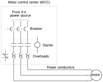 Motor Schematic Diagrams Wiring Diagram Tri Ac Motor Field Wiring Diagram Wiring Diagram